Design of Anchored Walls
For the design of anchored walls, if a suitable soil layer exists at a reasonable depth below the excavation to create an adequate bond zone for the anchor tendon (anchor reinforcement), both temporary and permanent anchored walls can be constructed in soft to medium clays (NS > 4).
Where soft clay is extensively present beneath the excavation base, permanent anchored walls (nailing) are rarely used.
Temporary Walls
When designing temporary walls in soft to medium clays, the Terzaghi and Peck diagram (Figure 1) is used to estimate the apparent earth pressure.
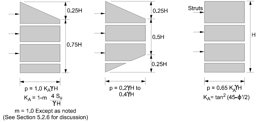
a) Sands
b) Fissured stiff to hard clays
c) Soft to medium clays
Figure 1. Apparent earth pressure diagrams – Terzaghi & Peck (1967)
In this method, m is an empirical factor representing the potential instability of the base in soft clay excavation support.
-
When the excavation is above deep soft clay and the stability number (NS) > 6, m is taken as 0.4.
-
Otherwise, m is taken as 1.0 (Peck, 1969).
However, as shown later, using the Terzaghi and Peck diagram with m = 0.4 for NS > 6 may underestimate the actual loads on the wall, making the design unconservative.
Terzaghi Diagrams and Base Failure Considerations
The Terzaghi & Peck (1967) diagrams do not consider base failure. Field observations and finite element analyses have shown that in such soils, base failure beneath the excavation can cause significant wall displacements in temporary retaining structures.
For NS > 6, if excavation induces large movements below the base, a considerable soil mass near the base may approach failure, increasing loads on the exposed wall section and risking base instability.
In this context:
-
d = depth to the failure surface below the excavation base
-
Su = undrained shear strength of the soil during excavation
-
Sub = undrained shear strength at depth d
Henkel’s Method
Figure 2 shows KA values calculated using Henkel’s method for various d/H ratios, assuming Su = Sub.
-
For 4 < NS < 6, the Terzaghi & Peck envelope with m = 0.4 is more conservative than Henkel’s method.
-
For NS < 5.14, Henkel’s method is invalid, and the apparent pressure calculated using m = 1.0 in Terzaghi & Peck is lower than actual values.

For the range 4 < NS < 5.14, a constant KA = 0.22 should be used to compute the maximum apparent pressure for soft to medium clays.
For NS = 4 (boundary between “stiff to hard clays” and “soft to medium clays”), the ultimate load using KA = 0.22 per the soft to medium clay diagram is 0.193γH².
For this ultimate load, the maximum apparent pressure from Terzaghi & Peck for fissured stiff to hard clays is 0.26γH.
Figure 2. KA values according to Terzaghi & Peck envelope and Henkel’s method
Henkel’s method is applicable only when the properties of the clay on the anchored side and beneath the excavation base can reasonably be represented solely by undrained shear strength. When additional shear strength parameters are required, limit equilibrium methods can be used to estimate earth pressures on the wall.