English Translation: Wall Behavior Analysis
Wall Behavior Analysis
The deflections of the northern wall show completely different patterns compared to those observed on the southern wall. As excavation progressed, the northern walls moved significantly inward, a behavior commonly seen in deep excavations.
Figures 1 and 2 illustrate the deflections of diaphragm walls during excavation in Sections 1 and 2. The maximum values are 26.2 mm and 50.9 mm, respectively. In contrast, the top of the southern wall moves outward while the bottom shifts inward. The maximum displacement at the beam crown in Sections 1 and 2 are -7.5 mm and -40 mm, respectively.
The deformation pattern of the diaphragm walls under symmetrical deep excavation is completely different, as shown in Figure 3. This distinct deformation may lead to strut instability. The unique deformation confirms that inclined loading increases the earth pressure acting on the northern wall.
The bracing system of the deep excavation needs to rotate to reach a new balance. Therefore, the earth pressure on the southern wall may shift from active to passive as it moves outward, making diaphragm wall deflections more sensitive to subsoil stability.
Figure 4 shows the relationship between maximum measured wall deflection (δh) and different excavation depths. The absolute deflections of the southern wall are illustrated. In both sections, δh for the northern wall increases linearly with excavation depth, ranging from δh = 0.14%H to δh = 0.27%H. δh for the southern wall is similar to the northern wall in Section 2. However, in Section 1, the southern wall deflection is very small, remaining under δh = 0.08%H during excavation.
The relationship between δh and H shows a significant decrease in δh when the bending stiffness of retaining walls improves. Nevertheless, despite using rigid concrete in this project’s diaphragm walls, the measured δh of the northern wall was still greater than those reported by Tan and Wei (2012) for soft clay excavation in Shanghai under similar bracing systems.
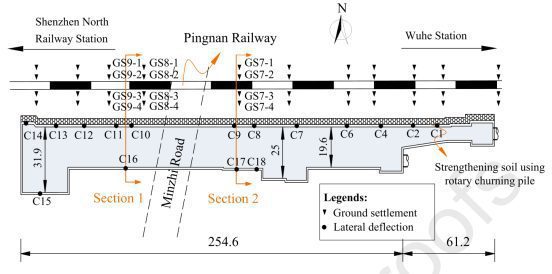
Figure 1: Deep Excavation Layout

Figure 2: Lateral Deflection of Diaphragm Walls

Figure 3: Deflection Modes of Diaphragm Walls
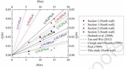
Figure 4: Maximum Wall Deflection at Each Excavation Depth and Stage