Jet Grouting
The jet grouting method combines hydraulic mining technology with advanced grouting techniques and has become one of the most popular soil improvement methods at various global sites. It is used to prevent soil failures, soil liquefaction, seal tunnel leakages, and construct cutoff walls.
Depending on the type of fluid jetted from the nozzles, jet grouting systems are classified into three types:
-
Single fluid system: high-pressure grout injection
-
Double fluid system: high-pressure grout and compressed air
-
Triple fluid system: high-pressure water, compressed air, and low-pressure grout
All these systems inject large volumes of high-pressure fluid into the soil, significantly increasing excess pore water pressure. This pressure rise, along with a temporary reduction in effective stress, may damage the surrounding ground. A notable example is soil improvement behind a gravity retaining wall, where the jet grouting device can temporarily generate strong forces.
Thus, accurately estimating excess pore water pressure during the jet grouting design stage is essential to mitigate its destructive impacts. This study proposes a theoretical approach to evaluate excess pore pressure generated during the installation of jet grouting columns in clay, throughout the construction sequence.
The column installation is modeled using a series of undrained expanded spherical cavities. Partial dissipation of pore pressure during the stepwise installation is also considered. A relationship is developed between the final cavity radius and the column radius to demonstrate how jet parameters and soil characteristics influence the generated pore pressure.
The proposed model is validated with two case studies:
-
Soft clay in coastal Singapore
-
Marine clay in Shanghai
In both cases, the predictions closely matched field measurements, confirming the reliability of the underlying assumptions and practical applicability of the method.
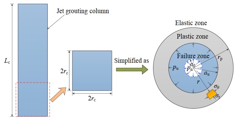
Figure 1: Schematic Diagram of Pore Water Overpressure Induced by Spherical Cavity Expansion
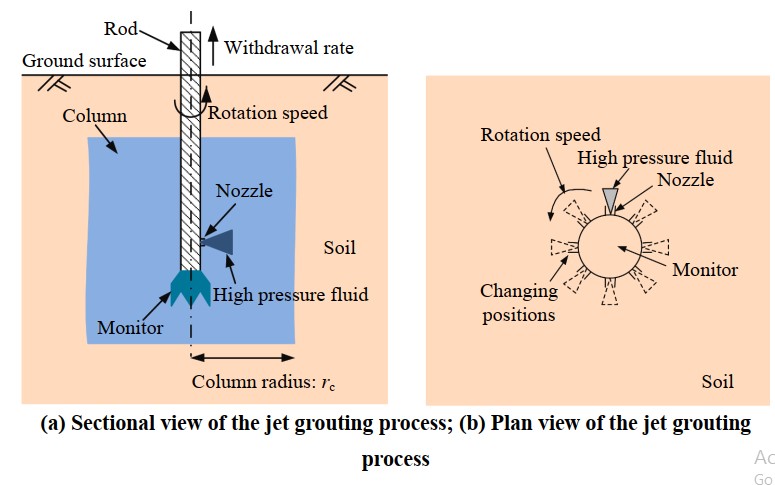
Figure 2: Cross-Section and Plan View Illustrations of the Jet Grouting Process