")
Introduction
Like many other geotechnical projects, surface water and groundwater flow can cause problems during construction, increase cost and construction time, damage the long-term integrity of the structure, and impair the performance of the stabilized wall by nailing method. To minimize these problems, the flow of surface and groundwater should be controlled both during construction and after the construction of the stabilized wall by nailing method. Also, when an effective and efficient drainage system is implemented to control the water level behind the stabilized wall, the stabilized walls by nailing method work significantly better. The following is a brief description of the drainage control systems used in walls stabilized by nailing method.
Groundwater and surface water control in the implementation of excavation stabilization by nailing method
Water drainage measures during construction include control of surface runoff and groundwater uplift or associated with local leakage areas. Drilling a surface water separation stream along the drilling crown, with a concrete cover applied during shotcrete of the first stage of excavation, is a recommended solution for controlling the flow of surface water in the implementation of a stabilized wall by nailing method. In addition, if design engineers believe that the effect of groundwater is local or short-lived, a well or well point behind the length of the nail (or nailing reinforcement) can be temporarily lowered the groundwater level. But this approach may lead to higher construction costs and delays in project scheduling.
Long-term control of groundwater and surface water in the implementation of excavation stabilization by nailing method
Geocomposite strip drains:
These elements are geosynthetic strips with an approximate width of 200 to 400 mm. They are placed in vertical rows along the entire depth of the stabilized wall in front of the drilling face. Usually the horizontal distance of the drains is equal to the horizontal distance of the nails (or nailing reinforcement). The lower end of the strips is inserted into a drainage pipe located along the bottom of the stabilized wall or through a weep hole in the stabilized wall floor.
For very irregular drilling face, it is difficult and often impractical to place prefabricated drainage strips in front of the drilling face. In some cases, prefabricated drainage strips may be sandwiched between the shotcrete cover and the permanent concrete cover in place, with drainage placed on weep holes 50 to 75 mm in diameter that have passed through the cover. To ensure that the drainage system is not damaged during shotcrete execution, it is necessary for the design engineer to provide clear instructions on the process of construction and supervision of this type of wall. If proper performance is not guaranteed, the effect of groundwater level must necessarily be considered in the analysis.
Surface drainage (weep holes):
Usually PVC pipes with a length of 300 to 400 mm and a diameter of 50 to 100 mm are removed from the cover and placed at the site of local leakage. Weep holes are also used at the end of the vertical drainage strips to drain the collected water through the stabilized wall.
Drainage pipes:
Horizontal or low-slope drainage pipes may be installed where it is necessary to control the groundwater pressure applied to the retaining soil mass. Drainage pipes usually consist of prefabricated or mesh pipes made of PVC with a diameter of 50 mm, which are installed at an angle of 5 to 10 degrees to the horizon.
Drainage pipes are usually longer than the length of the nail (or nailing reinforcement) and are sufficient to prevent groundwater from coming into contact with the nail (or nailing blocker) or the nail block (or nailing). The length of the drains depends on their application. Drainage pipes with a length of 0.3 to 0.5 m and in some cases, 1 m can be installed to provide a drainage surface or drainage of intrusive water (silver) that is present near the cover.
The approximate density of drains is one drain per 10 square meters of cover. To prevent the slurry from penetrating into the mesh pipes, drainage pipes are usually installed after the nails (or nailing reinforcement) are applied. The pipes are usually located between the covering and the stabilized wall.
PVC pipe should be mesh type. Although drainage pipes are usually installed after the nails (or nailing reinforcements) have been installed and the shotcrete has been applied to prevent slurry or shotcrete from entering the pipes, they can also be installed before the shotcrete has been applied. In this case, a dry-pack cap and temporary PVC caps should be used to prevent shotcrete from entering the drain pipe holes and blocking the mesh pipe holes.
Permanent control of surface water:
Permanent surface water control measures include installing a separating and diverting stream behind the stabilized nailing (or nailing) wall to prevent surface runoff from penetrating behind the stabilized nailing (or nailing) wall or flowing over the edge of the stabilized wall. Vegetation may also be used to reduce or delay and repel water infiltration into the soil.
Prefabricated drainage system in excavation stabilization
Prefabricated drains in excavation stabilization (vertical drains) are considered as wick drains that contain a synthetic core located in the geotextile layer. Figure 1 shows a prefabricated drainage system used to accelerate consolidation in excavation stabilization (excavation stabilization by guard structures, nailing, anchorage, top down, etc.).
These types of drains used to improve the stabilization of the excavation (stabilization of the excavation by guard structures, nailing, micropiles, anchorage, top down, etc.) are very suitable in clay, silty, organic layers, silty and clayey sands. These drains are first placed inside the mandrel and then the mandrel is inserted into the ground to the desired depth. The anchor plate is attached to the prefabricated drain so that the drains remain in the ground until the mandrel is removed from the ground. Then, the drains are cut slightly above ground level.
Properties of prefabricated drains to accelerate solidification in pit stabilization
1.flexibility
2.High durability
3.to be cheap
4.No need to dig for installation
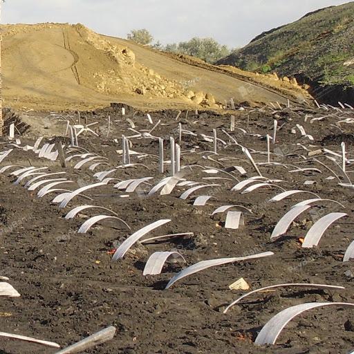
figure 1. Prefabricated drainage system used to accelerate consolidation in excavation stabilization (pit stabilization by guard structures, nailing, anchorage, top down, etc.)
Functions of prefabricated vertical drains in soil improvement
1.Reduces the preloading process.
2.Accelerates the action of the consolidation settlement.
3.pore water comes out of the soil horizontally from the nearest drain instead of entering the substrate vertically.
4.Reduces the drainage path.