")
-
Tieback systems are divided into various types including nailing, anchoring, and Berlin wall systems, which are comprehensively described below:
- Defining nailing
Soil nailing system involves reinforcing (not post-tensioning method) the ground by installing and executing steel rebars close together (nails or reinforcing nails), which are subsequently anchored into the slurry. To ensure the continuity of the stabilized wall during the progress of its construction from top to down, the excavation wall is shotcrete. This system is commonly used to stabilize natural slopes or excavations. Under certain conditions, the earthen wall nailing system is a suitable solution from the point of view of technical feasibility, construction costs and execution time in comparison with the ground anchor system, which is another conventional retaining system (top-down). This technique is 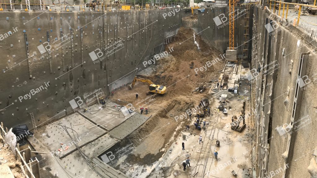 also used for excavation in soil-like materials (eg, soft rock or aerated rock).
Another application of the passive reinforcement system is in landslide stabilization. In this case, the reinforcement system (nail, nailing or passive nails) is implemented in a pattern close to each other and almost perpendicular to the slip bed and is exposed to shear forces due to the movement of the sliding mass. A structure can be divided into permanent or temporary structures based on its service life or intended time of use. A structure with a service life of 18 months or less is known as a temporary structure and a structure with a longer service life is known as a permanent structure. If a structure was originally intended as a temporary structure (for example, an excavation temporary maintenance system) but its construction is delayed so that the excavation remains without a reinforcement and maintenance system for more than 18 months, the structure should be constructed as a permanent structure.
- Background
Origin of nailing wall
The origin of the nailing wall can be related to the retaining system of underground rock drilling known as the New Austrian tunneling method (Rabcewicz, 1964a, 1964b, 1965). This method involves the implementation of a passive steel reinforcement system in rock bolt. The combined system of passive and shotcrete reinforcing steels has also been used since the late 1960s (Lang, 1961) to stabilize rock slopes. Stabilization of rock slopes is used. This technique relies on the tensile strength of reinforcing steels under relatively small deformations in the ground and surrounding soil. This system is upgraded by shotcrete connectivity. If a combination of passive and shotcrete reinforcing steels is used instead of rock in the soil, it is called nailing.
One of the first applications of the soil nailing system was in 1972 for a railway widening project near Versailles, France, where an 18-meter-high sandy roof was stabilized using a nailing system. Because this method was cost-effective and had a shorter construction time (Rabejac and Toudic, 1974) than other conventional systems, the use of soil nailing systems became common in France and other parts of Europe.
The first use of the nailing system in Germany dates back to 1975 (Stocker et al., 1979). The first major research project on wall nailing in Germany performed from 1975 to 1981 at the University of Kalsruhe and the Boer construction company. The research program included full-scale experiments of laboratory walls with different arrangements and the development of analysis and design methods. (Gässler and Gudehus, 1981; Schlosser and Unterreiner, 1991) .
In France, the Clouterre research program began in 1986 with public-private partnerships. The purpose of this study was to perform full-scale experiments, study and monitor structures in operation and numerical simulations (Schlosser, 1983; Clouterre, 1991).
History of Application and Development in the United States
The first use of a nailing wall system in North America was for temporary maintenance of excavated excavation in Vancouver, Washington, and Mexico City in the late 1960s and early 1970s. One of the first applications in the United States was to maintain a 13.7-meter-deep foundation drilling system in dense lake silt sand for the development of the Good Samaritan Hospital in Portland-Oregon in 1976 (Byrne et al, 1998).
According to reports, the construction of this protective system took about half the time and 85% of the cost of conventional drilling 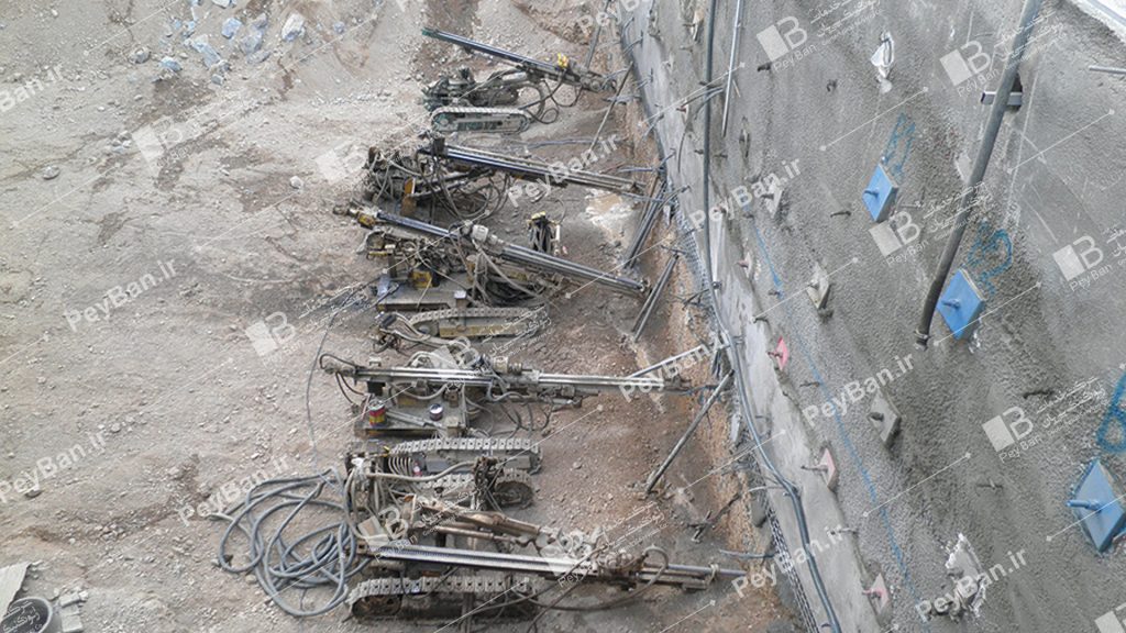 maintenance systems.
In 1989, the Oregon Department of Roads and Transportation, as the first application of a soil nailing system, installed an 8-meter wall at the bridge abutment (end-slope removal). In 1988, a 12.2-meter double-layered wall was built along Interstate 78, near Alton, Pennsylvania. Each row of walls with a height of 6.1 meters with a horizontal displacement of 3 meters, was made of very aerated rocks.
The use of nailing stabilized walls has increased in the United States over the past decade, mainly for the following reasons;
- This system is technically feasible.
- In most cases, it is economical compared to conventional retaining walls that are performed from top to down in permanent and temporary excavations.
Design engineers are becoming more familiar with soil nailing technology. Most nailed stabilized walls are still used as temporary retaining structures, but the use of a nailed system as a permanent structure has increased in the last ten years.
The development of knowledge and application of the soil nailing system owes much to the efforts of the US Highway Administration’s R&D department. The first documents on soil nailing were published by the U.S. Department of Highway Research and Development (Elias and Juran, 1991). The purpose of this document was to disseminate information to US highway consulting engineers and users who used the technique as a buffer system in transit projects.
These efforts paved the way for further research and development activities in the United States. In 1993, the U.S. Highway Authority paid for the translation of the French text “Implementation of the Soil Nailing System” into English. In 1994, the “Monitoring the Earth Wall Nailing System” was published (Porterfield et al, 1994). From 1996 to 1998, the U.S. Department of Highways and State Consulting Engineers supported all workshops nationwide to provide executive guidance for the nailing system. The documents collected from 103 experiments were presented as a preliminary design guide and subsequently developed as a design guide (Byrne et al., 1998).
The U.S. Department of Highways has also established various research projects in academic societies.
General Anchorage System
The prestressed injection reinforcement (or reinforcement anchor) is actually a structural element implemented in the soil or rock, whose role is to transfer the applied tensile load to the soil mass. First, the boreholes are drilled in the face of the wall, and after the placing the anchor reinforcement, a slurry injection operation is performed and the boreholes are filled. Injection restraints (or armature reinforcements) are also called tiebacks.
Note: It is appropriate to review the concept of pre-stressing again, means applying stress to the load-bearing element before operation. That is, before the load-bearing structure and element are exploited and the final dead loads of the structure and live loads are exploited and other loads are imposed on the structure and element, tension is created in it by pulling the member (rebar or cable). Note, therefore, that it is referred to as “pre-tensioning” due to implementing the stress on the member before operation.
Pretensioning is done in two ways, “pre-stretching” and “post-stretching”. If the stretching process takes place before concreting or grouting, then we say, “prestressing.” But if after concreting or grout injection, stretching occurs, then we say ” Pretensioning is caused by post-stretching”.
The main components of the injection anchorage system
The main components of the injection anchorage system (or anchorage in the nailing system) consist of three parts; 1) “restraint set (or anchor reinforcement)” 2) non-bonded length or non-stress length and 3) bonded length. “Anchor (or anchor armature) set” includes “anchor head (or anchor armature)”, bearing plate and horn. The role of the “anchor assembly (or reinforcement armature)” is to transfer the prestressing forces from the prestressed steel (steel rebar or strands) to the wall surface (ground surface) or supporting structures.
The material of the bracing element (or anchorage reinforcement) can be selected from rolled rebars or woven steel strands. In fact, the restraining element (or anchorage reinforcement) is divided into two main groups according to the type of material. If the restraining (or anchoring) material is rebar, then the saddle is called a “rebar tendon”, and if the restraining (or anchoring reinforcement) element is made of steel strands, it is called a “cable tendon”.
In the “anchor assembly (or anchor reinforcement)” for the rebar tendon and the cable tendon, the non-bonded length is a part of prestressed steel that does not increase in elastic length and transfers the resistive force from the bond length to the structure. A bonder is a smooth plastic sheath that encloses steel rebars or filaments along a non-bonded length to prevent slurry from adhering to the prestressed steel in this section. The presence of this plastic sheath allows the prestressed steel located in non-bonding length to be easily extended during friction and stress tolerance without any environmental friction, and thus the prestressed steel is still considered non-bonded after the lock-off load is applied. The bond length of the tendon is the length of the prestressed steel that is surrounded by the slurry and is able to transfer the applied tensile loads to the surrounding ground. The bond length of the restraint (or anchor reinforcement) must be behind the critical rupture level.
As mentioned, the “tendon” is part of the set of anchoring system (or anchoring in the nailing system) in the soil. The tendon (or restraint element) consists of a prestressed steel element (rebar or steel strands), a corrosion protector, sheath, concentrator, and spacer. Note that the slurry is not part of the tendon (element) complex. The sheath is a flat or corrugated tube that protects the prestressed steel located along the non-bonded surface from corrosion. Concentrators hold the tendon in the center of the borehole to provide minimal slurry coverage around the tendon. In multi-element tendons, spacers are used to hold the steel strands or rebars apart, so that each element is adequately and appropriately surrounded in the injected slurry. The slurry is made of Portland cement, the main role of which is to transfer load from the tendon to the surrounding soil and also protects the tendon from corrosive factors.
- Material definition
- Tendon materials
- Rebar tendon and cable tendon
Nowadays, in bracing (or anchoring in nailing system) soil and stone, rebar or steel cable is used as a restraining element (or anchoring reinforcement). Specifications (standard) for rebar and steel cable are ASTM-A722 and ASTM-A416, respectively. ASTM-A886 is also the specification booklet for prominent steel strings. The rebars used are mainly in diameters of 26, 32, 45 and 64 mm. They are in 12 and 18 meter branches that couplings can be used to restrain (or reinforce anchors) taller ones. Fingerprint can be said to be an integrated 18-meter rebar tendon (without coupler) with a diameter of 64 mm is capable of carrying a load of 2077 kN. Compared to steel strands, rebars withstand more stress and the load applied to them can be adjusted after the lock-off process.
Steel strands consist of several “seven-wire” filaments. The most widely used steel strands in the United States are cables with a diameter of 15 mm. Multi-stranded cables have no restrictions on loading or length of restraint (or anchor reinforcement). Steel strands have good properties that lead to long-term stability of the load-bearing capacity (or reinforcement anchorage). If long single-wire strands are used, the priority is to use factory-made long cables, in this occasion, a coupler can also be used. The use of a coupler is not recommended when the diameter of the coupling is much larger than the diameter of the filaments, but a coupler can be used to repair defective tendons. When using a coupler, the issue of tendon corrosion protection at the patch site should be considered.
1) Separators and concentrators
During the connection, a spacer (concentrators) is usually placed every 3 meters. For multi-strand cable tendons, spacers should have a minimum spacing of about 6 to 13 mm between strands and a minimum coverage of 13 mm should be provided for slurry around the strands. Separators and concentrators should be made of corrosion-resistant materials and should not impede the free movement of the slurry during injection.
Epoxy coated steel rebars and filaments
Epoxy coated rebar (AASHTO M284) and epoxy coated steel cable (ASTM A882) are not widely used in road construction projects but are widely used in dams. The epoxy coating creates a double layer of corrosion protection during bonding and non-bonding of anchor (or anchoring reinforcement).
In epoxy coated steel cables, in addition to the perimeter of the strands, the gap between the seven wires in each strand is also filled with epoxy. It is not recommended to use cables where the distance between the wires is not filled with epoxy coating, as water may enter the gaps between the strands and cause them to corrode. Unlike non-epoxy filaments, the creep deformation in epoxy coated filaments is relatively significant during the anchorage (or anchor reinforcement) test. In evaluating the criterion of anchor creep and to obtain the exact amount of the displacement in the bonded region, the creep of the epoxy coated filaments must be deducted from the total creep displacement. How to accurately calculate the creep displacement of epoxy coated filaments is presented in the journal PTI (1996).
2) Other types of restraints (or anchorage reinforcement) and tendon materials
In addition to bracing (or anchoring reinforcement) prestressed injected steel, other types of anchoring (or anchoring reinforcement) and materials are used in the United States. Examples include 60- and 75-degree rebars by grout injection, star restraint (or reinforcement of star anchors), plates bracing (or reinforcement of anchorage), and mechanical restraint (or reinforcement) of rock. The design methods and test methods discussed in this paper are specific to the bracing (or reinforcement of anchorage) of high-strength prestressed steels. These methods are not suitable for the other types of anchors (or reinforcement anchors) mentioned above.
In recent decades, research has been conducted on the use of reinforced plastic tendons (FRP) (Schmidt et al., 1994). FRP tendons have high tensile strength, they have high corrosion resistance, and also are lightweight. Other materials, such as fiberglass and stainless steel, have also been used in the laboratory, but cost and implementation problems have limited the development of their use.
Cement slurry
The slurry used for the bracing (or anchor in the nailing system) in the soil is usually pure Portland cement slurry (slurry free of any additives) according to ASTM C150 standard. However, sand-cement slurry can also be used for large diameter boreholes. Sand-cement-pea slurry can also be used to inject encapsulated enamels. The use of high speed mixers can guarantee uniform mixing of water and slurry. The weight ratio of water to cement (W / C) is between 0.4 and 0.55. When stress is applied to the restraint (or anchor reinforcement), type I cement typically provides a minimum compressive strength of 21 MPa. In some projects, special additives may be required to improve the performance and flowability of the slurry. No additive is often needed, but in cases where the ambient temperature is high or the slurry pumping distance is very large, the use of lubricant can be helpful.
Related articles
What are the advantages and disadvantages of nailing walls?
What are the uses of the wall nailing system?
What long-term or short-term considerations should be considered in the design of excavation stabilization by nailing method?
How to control surface and groundwater in the implementation of nail stabilization by nailing method?
Design considerations of stabilized nailing wall
What subsurface surveys are required to implement the nailing system?
What is the distribution of tensile force in nails or nailing reinforcements?
What is the distribution of load on the nailing wall?
How to monitor a stabilized wall by nailing?
Evaluation of the adequacy of executive operations in the stabilization of the excavation by nailing method