")
What is micropile?
Generally, in the face of problematic soils such as loose soils with low bearing capacity, high settling capacity, liquefaction, manual soils, etc., there are two ways for geotechnical engineers:
- A) Using the load-bearing elements in the soil
- B) Improvement and modification of physical-mechanical properties of soil mass.
Each of the above solutions has its methods and specifications that have been developed over the years. Some innovative techniques also have the nature of a combination of the above two categories and have the advantages of both categories to some extent. Among them, we can mention the use of micropiles with the injection of cement slurry.
Piles are generally divided into two main groups: displacement piles and replacement piles. Micropiles are small replacement piles (usually less than 300 mm in diameter) that are often associated with light steel reinforcement and cement slurry injection. Micropiles can be designed and implemented from any angle and can be used for a variety of purposes, including bearing axial and lateral loads, replacing conventional piles, or as part of a combined soil-pile system, depending on the design goal.
Micropile in addition to acting as a load-bearing element and resistant to settlement, due to the injection of cement slurry, also improves the strength characteristics of the surrounding soil.
Micropile is a small diameter pile with a light steel reinforcement in which the cement slurry injection technique is used. According to the FHWA regulations, micropiles are less than 30 cm in diameter, while in Iran they are typically about 8 to 15 cm in diameter.
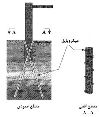
The components of the micropile system in Iran include casing, reinforcement, and flange connecting to the foundation and cement slurry. The casing has holes at appropriate intervals that allow injection under pressure into the soil.
The construction of the micropile system also includes the steps of drilling a borehole, placing a casing in the soil, injection of cement slurry, installation of reinforcement, and installation of a connecting flange, which are described in the following sections.
History of micropiles
Micropiles were invented in Italy in the early 1950s to reinforce the foundations of historic buildings that had been damaged over time, especially during World War II. An Italian contractor named Fondil first introduced root piles. These small in-situ piles were small in diameter, often reinforced with light steel reinforcement and cement slurry injection.
Initially, most applications of micropiles were limited to reinforcing existing infrastructure in urban environments, but in 1957 new engineering needs leading to the introduction of new systems called micropiles called reticulate micropiles. It is a three-dimensional network of vertical and oblique micropiles that form a composite structure of soil and pile and is laterally bounded.
Foundil (1962), used this method to strengthen historic buildings in England. Also in 1965, this method was used in the German underground transport system, after which the term micropile replaced the name of the root pile. These micropiles are used to stabilize slopes, reinforce coastal walls, protect buried structures, reinforce soil, and other soil and structure reinforcement methods.
Micropile implementation steps
The method of micropile implementation includes four stages of drilling, Pile driving, injection, and reinforcement, the steps of which are described below.
Drilling
In general, micropile pipes are placed either by percussion or drilling. Placement through percussion significantly improves the bearing performance of micropiles due to the friction between the pipes and the surrounding soil wall and its effect on increasing the injection pressure of cement slurry. Placement through drilling causes corrosion in different layers of soil and practice, a larger diameter should be drilled than the outer diameter of the pipes. For this reason, drilling operations are used only in situations where pipe drilling is not possible (mainly at great depths). Drilling operations are carried out in different methods such as rotary drilling or down the hole drilling (D.T.H).
Pile driving
After drilling, micropile pipes are hammered in the specified places by pile driving machines. The pipe of the first piece is bayonet and the next pieces are completely connected by socket and welding, respectively. The pile driving operation will continue as long as it is possible to knock the pipes, and if the pipe does not sink more than 10 cm for 30 consecutive blows, the pile driving operation will be stopped.
In this case, drilling is done until the depth of the design is realized and then the pipes related to micropile are installed inside the borehole.
Micropile pipes have an outer diameter of 76 mm and an inner diameter of 68 mm in two-meter pieces. These pipes are connected by socket and welding. Each micropile has 80 holes with a diameter of 8 mm per meter. The internal environment of the pipes should be برقوزده so as not to have negative effects on grout injection.
Injection
Injection devices consist of three parts: primary mixer, secondary mixer, and injection pump. Mixing in the primary mixer is of the rapid water circulation system type and the secondary mixer is of the vane type. The injection slurry is made in the primary mixer by first pouring the desired amount of water into the mixer and then adding cement to the required ratio of water to cement. The minimum mixing time of cement slurry is 30 seconds. The ratio of water to cement used is between 0.5 and 1.5 depending on soil conditions. After preparing the slurry, for maintenance, the slurry is poured into the secondary mixer and then injected by special injection pumps. To inject the slurry into the micropile pipes, special hoses called a packer are used, which when injected, the packer sticks to the wall of the pipe and prevents the slurry from leaving.
For example, the first step of closing the packer for the 8-10 m micropile is at a depth of 6 meters. After the injection operation at a depth of 6 meters, the packer is closed at a depth of 4 meters, and after the injection is completed at this stage, the packer is closed at a depth of 2 meters, and finally, after injection at this stage, the wellhead packer is closed and the injection operation is completed.
Injection specifications
Injection pressure: Injection pressure can vary at different injection stages and depths, under the influence of soil type and geotechnical conditions. The maximum injection pressure is limited to 10 atmospheres
Amount of cement used: Depending on the geotechnical conditions and the load-bearing capacity of the micropile design, the estimated amount of cement can be equal to each micropile length up to 100 kg. However, since the injection should be continued up to a pressure of 10 atmospheres, so the amount of cement may be higher than the initial estimate.
Water to cement ratio: The water to cement ratio in the injection slurry used can be between 0.5 and 1.5 under normal conditions and the water to cement ratio of the slurry in other conditions can vary from 0.67 to 1. It should be noted that the slurry ratio in each section is determined at the suggestion of the contractor and the approval of the monitoring device.
Type of cement used: The type of cement used in cement injection mortar is Portland cement type I, type II or type V cement, which is determined according to the chemical conditions of the desired location.
Water used: The water used in the preparation of slurry should be clean and smooth and has all the necessary conditions for water consumption in concrete construction. Water used must be free of any substances such as acids, alkalis, sugars, salts, and organic matter that can damage the concrete. The water used in the manufacture of injection slurry should have suspended solids less than 0.2%, soluble substances less than 3.5%, chlorine content less than 1%, sulfate content less than 0.3%, and alkali content less than 0.06%. In general, drinking water is suitable for making a slurry.
Arming and installing flanges
In the case of bearing micropiles, it is necessary to place the reinforcement inside the micropile tube and install the flange. The reinforcement must be installed inside the borehole before the cement setting.
The flange, which is used to create a complete connection between the micropile and the foundation concrete, as well as to prevent cone shear of the micropile head inside the foundation concrete, must be welded to the micropile reinforcement in the last step.
Optimal conditions in the implementation of micropiles
Various factors are effective in selecting micropiles for the foundation and slope stability. These factors include:
- Physical condition
Access restrictions in remote areas
Proximity to existing buildings
- Underground conditions
Difficult geological conditions;
Lands prone to liquefaction during pile installation
- Environmental conditions
– Vibration and noise-sensitive areas;
– Dangerous or contaminated soils
- Compatibility with existing structures
- Limitations of micropiles
- Economic conditions
Physical conditions
The drilling and injection equipment used to install the micropile is relatively small and can be installed in confined areas where it is not possible to pass the pile installation equipment. Micropiles can be installed inside walls and foundations with dimensions of several millimeters. their installation is not affected by their upper force or other obstacles in the installation of piles.
Installation equipment can move in areas with steep slopes as well as remote areas. Also, drilling and injection operations related to the installation of micropiles will not cause damage to adjacent buildings if performed properly.
Subsurface conditions
Micropiles can be installed in areas with harsh, variable, and unpredictable geological conditions, such as lands with cobble and boulder and underground facilities, or the presence of various debris and irregular lenses of weak materials and components.
Soft clays, sand dunes, and high groundwater levels, which are considered unfavorable conditions in the traditional installation method, have the least impact on micropile installation. Micropiles are used worldwide in karstic calcareous formations.
Environmental conditions
Micropiles can be installed in hazardous and contaminated soils. Their small diameter reduces the amount of losses during installation compared to traditional replacement piles. The slurry mixture can be designed to be resistant to the chemical activity of water and soil. In the slurry mixing scheme, additives can be used to prevent the deterioration of concrete in acidic and corrosive environments.
Micropiles can be installed in sensitive areas, such as areas of fragile nature. Their installation equipment is not as large or heavy as ordinary drilling and pile installation equipment and can be used in sludge fields or other areas with soft and moist surface soil, with minimal impact on the environment. Portable drilling equipment is commonly used in restricted areas.
Installing micropiles creates less noise and vibration than conventional traditional pile installation techniques such as pile driving. Vibrations generated during drilling are transmitted first to the soil and then from the soil to adjacent buildings. The use of micropiles in old and industrial urban areas can prevent this destructive effect on sensitive equipment and adjacent structures.
Micropiles can be installed in areas where a contaminated aqueous layer is located on a load-bearing layer. Unlike driven piles, which may create a vertical conduit for contamination, micropiles can be installed in such a way as to prevent contamination of the underlying aquifers.
Compatibility with existing structures
Micropiles can be added to existing pile caps. Therefore, the need to increase the dimensions of the foundation is eliminated. This action provides additional compressive, tensile, and flexural strength requirements when increasing the load on the structure. Sometimes the limitations of adjacent structures do not allow us to increase the dimensions of the existing pile cap. Therefore, the need for conventional candle installation systems is eliminated.
Limitations of micropiles
In some cases, vertical micropiles may be limited in terms of lateral bearing capacity and cost reduction. They are also assumed to have limited axial bearing capacity due to their small relative diameters. Although in the experiment, the micropiles have withstood an axial load of 4,500 kN in dense sand, so it is expected that further lateral load capacity will be increased with further research and testing. The ability to install micropiles obliquely helps designers to achieve the required lateral bearing capacity. The cost of implementing micropiles is usually higher than traditional pile installation systems, especially driven piles. But in some special cases, micropiles are an economical option and at the same time the only possible solution for building and executing a project. The use of micropiles in stabilizing slopes at limited altitudes has been based on past limited experiences. Due to the limited number of implemented projects, it is recommended that slopes be instrumented and monitored in stabilization applications.
Economic conditions
The economics of micropiles depends on many factors. It is very important to evaluate the cost of implementing micropiles with respect to the physical, environmental, and subsurface conditions described above. For example, for a site with soft, clean, uniform soil and easy access, micropile However, for sensitive foundations under bridge piers in old residential or industrial areas with heavy traffic, micropiles can be considered as an economical solution.
The slurry mixture can be designed to withstand the chemical activity of water and soil. Special compounds can be used in the design of the slurry mixture to increase its resistance to acidic and corrosive environments.
Cost analysis should be done taking into account all costs related to the project and not just the costs associated with the installation of piles.
These costs may include the following:
Drilling, pile driving, and embankment requirements;
Execution of foundation;
Carrying hazardous materials;
Lowering the groundwater level;
Erosion control;
Access restrictions;
Land improvement and…
Applications
According to the explanations provided in the previous section, the use of micropiles can be generally expressed in the following two sections:
- Use of micropiles as a load-bearing element
- Use of micropiles with the aim of soil improvement
The primary use of micropiles is as a load-bearing element. Many studies have been done in this field and its design methods are also available in various sources. But unlike the first part, the use of micropiles with the aim of soil improvement is a new issue that has been raised in recent years and limited studies have been conducted on it. Currently, in Iran, micropiles are used in the following four areas:
– Used as a load-bearing element under the foundations of buildings
– Used as a load-bearing element to repair the foundations of old buildings
– Used as a load-bearing element under the foundation of other superstructures (bridge abutment, oil and gas tanks, etc.)
– Used to improve the soil and increase its resistance and behavioral parameters
 – Used to improve the soil and deal with the phenomenon of liquefaction
Micropile classification system
The classification of micropiles is based on two criteria:
-How to design
-Procedure
Classification by design type
The design of a single micropile or group of micropiles is very different from the design of reticulated micropiles. This has led to the definition of two design categories for micropiles. In the first category, micropiles are loaded directly and the reinforcements bear most of the applied load. In the second category, micropiles are placed in the soil as a network and create a reinforced soil composite system that can withstand the applied loads. This hybrid system is the same network of reticulated micropiles.
In the first category, micropiles are used as an alternative to traditional piles to transfer the load of the structure to the underlying resistant layers. These micropiles are designed to perform individually, even if run in groups. In the second group, micropiles have lighter reinforcement because the reinforcers, like the first group, are not directly loaded and it is the mass of soil and piles that bears the applied loads. In addition to these two categories, another type of micropile is used in Iran, which is known as consolidation micropile. Consolidation micropiles are similar to network micropiles in terms of behavioral philosophy, except that it does not use reinforcement. Cement slurry injection is the main part of consolidation micropile, which increases soil resistance and behavioral parameters.
Classification based on the implementation method
The injection method is the most important factor affecting the bond resistance between the ground and the slurry. In such a way that the resistance of the band changes directly by changing the injection method. In this classification, the criterion is the injection method and its pressure, and the use of sheaths and reinforcements determines the sub-sections of this classification. In this classification, micropiles are divided into 4 categories.
Type A: In this method, the slurry is placed under its weight.
Type B: In this method, the cement slurry is injected into the borehole under pressure after the steel sheath comes out of the borehole. The injection pressure usually varies between 0.5 and 1 MPa and should be such as to prevent hydraulic failure.
Type C: Type C represents a two-step process in which the cement slurry is first placed under its weight inside the cavity (as in type A). Then, before the initial slurry hardens (after about 15 to 25 minutes), the same type of slurry is injected, at the point of contact of the slurry with the ground and at a pressure of at least 1 MPa through the lattice injection pipes without the use of a packer. This type of micropile is used only in France.
Type D: Type D is a two-step injection process similar to type C, but with changes in the second step. First, the cement slurry is uniformly placed under its weight, such as type A and C, or under pressure, such as type B, in the cavity. After the initial slurry hardens, the next slurry is injected through lattice injection pipes at a pressure of 2 to 8 MPa. In this method, the packer is used so that special surfaces can be modified several times if necessary.
The construction of micropile system has special advantages in comparison with other methods of foundation construction and soil improvement, which can be considered as follows:
- It requires less equipment than prefabricated or in-site pile construction equipment.
- It can be used in lands that have limited working space (for example, in the basement of old structures or under the decks of bridges, etc.).
- It has high execution speeds.
- It is easy to work with its equipment.
- It can be used to increase the bearing capacity of existing foundations because of its high flexibility.
- It can be used in urban environments due to less noise and vibration caused by the installation.
- It is easy to perform various tests on it, such as compressive, tensile, and lateral loading tests.
Principles of micropile design
The principles of micropile engineering calculations depend on the micropile usage type and its behavior. In the case where micropiles are used to consolidate and improve the foundation of structures, the technical calculations of micropiles are similar to the calculations of conventional piles. These calculations are based on three parts: structural design, geotechnical design, and cone shear control.
In the structural design, the bearing capacity of micropile elements including steel wall, reinforcement, and cement slurry is calculated. This capacity should be higher than the load applied on the micropile.
In the geotechnical design, the frictional resistance of the micropile wall with the surrounding soil is calculated. This friction resistance should be higher than the applied load to prevent the micropile from separating from the soil before the surrender of the reinforcing agents.
In the final step of the design, since the micropiles have a high concentrated load and small diameter and the cone shear is possible due to the 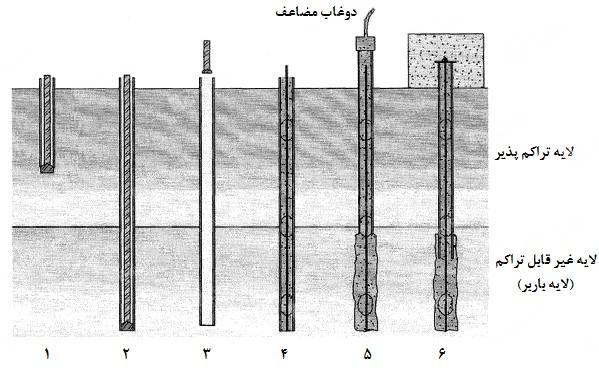 applied overheads, control of the resistance against cone shear is performed, which leads to a suitable flange design.
Design methods
Service load design (SLD) or allowable stress method
In this design method, which is often used by geotechnical engineers, the design is such that the allowable load is always greater than the design load.
Load factor design (LFD) method
In this method, using factors of load increase and decreasing resistance, the design is done in such a way that the design resistance is always greater than the required resistance.
Both design methods try to compensate for the uncertainties in the load and the properties of soil and materials that arise from their inherent random nature by applying a coefficient of reliability.
Performance quality control
To ensure that the micropiles are capable of withstanding the intended design load without additional displacement and with sufficient reliability during their service life, a field load test is performed on the micropiles.
In addition, using these tests, it will be possible to control the performance of the contractor during execution and after drilling, installation, and injection operations.
The following purposes are considered in all loading tests:
Achieve a predetermined maximum load;
Achieve a predetermined axial displacement;
Achieve a predetermined creep threshold;
Loading tests are divided into four general categories:
Final test: In this test, the load continues to the point of rupture between the soil and the slurry (without increasing the load, the displacement increases).
Verification test: This test is performed to check whether the execution method is capable of supplying the intended band resistance. The magnitude of the test load is determined according to the considered reliability coefficient. For example, if a reliability coefficient of 2.5 is considered, the test load is 250 times the design load. In the validation test, the micropile does not necessarily reach the rapture point. This test is usually performed on the Ghorbani’s micropile before construction begins. It is also performed during implementation to determine capacities in different soil conditions and different methods.
Proof test: This test is usually performed on a percentage of micropiles (about 5%). This test is performed by increasing the step load to a percentage of the design load (recommended by Regulation 167). The micropile ability to withstand service loads without large displacement is controlled using this test.
Creep test: This test is usually performed in addition to the previous three tests (final, verification, and proof). The creep test involves measuring the amount of displacement, at a constant load, and specified intervals. A maximum displacement of about 2 mm at each time point is the acceptance criterion. The purpose of this test is to evaluate the safety of the system against design loads during operation.