")
To solve the problems of liquefaction, settling and capacity of structures, construction techniques similar to micropile, jet grouting, pile execution and deep soil mixing are recommended, which are briefly described below :
Definition of micropile
Micropiles are divided into two general groups: “prefabricated micropiles” and “in situ micropiles” (Fleming, 1985). Prefabricated micropiles are elements that are pushed into the ground by impact or vibration, so during installation, they move the surrounding soil and push it forward. In-site micropiles are placed in pre-drilled boreholes and wells, or built and executed on site. So they are placed in the excavated ground.
Micropiles is often a component of in-site and drilling piles with a small diameter (usually less than 300 mm) that are often reinforced with reinforcement. Micropiles is installed by drilling a borehole or well, then placing the reinforcements in the borehole, and finally injecting the 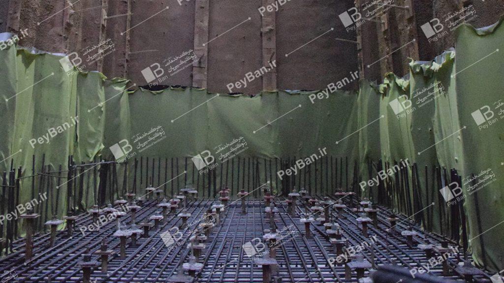 borehole.
Micropiles are able to withstand axial and lateral loads and can replace conventional piles or be used in conjunction with a pile system, depending on the design method. Micropiles are performed in ways that cause minimal damage to the soil, structure, and surroundings. They can be installed in difficult access environments and in all types of soil and ground conditions. Micropiles can be installed at any angle to the horizon using the same equipment used in injection and anchorage projects.
Because the implementation process creates little vibration and noise and can be installed in low-ceilinged spaces, it is often used to strengthen the foundations of existing structures. In cases where the underground space is limited, special drilling equipment is required.
Most of the forces applied to in-situ piles are mainly supported by reinforced concrete. In this regard, to increase their structural bearing capacity, the cross section and contact surface of the pile can be increased. In contrast, the structural bearing capacity of a micropile relies on the capacity of its durable steel elements. These steel elements occupy about half of the borehole volume. The use of special drilling and injection methods in the implementation of micropiles increases the load capacity in the soil-slurry complex.
The slurry transmits the forces in the bonding area (soil-slurry complex) to the ground in a manner similar to ground bracing, through friction and with the help of reinforcements. Due to the small diameter of the micropile, the bearing capacity of the tip is generally neglected.
The strength of the slurry-soil bonding area depends on the type of soil and the method of injection (for example, compression or gravity injection). The drilling method is also effective.
Installation steps of micropile using pipe jacketing
1) Start drilling or install temporary jacket 2) Continue drilling to the final depth 3) Extract the drillbit and rod 4) Installation of reinforcement or other reinforcement systems and Tremie grout injection 5) Temporary jack extraction and injection of secondary grout under possible pressure 6 ) Completing the piling (the jack may remain in the compressible layer)
- History
Micropiles appeared in Italy in the early 1950s to strengthen historic foundations and monuments that had been damaged and destroyed over time, especially during World War II. At that time, a reliable system was needed to maintain the loads and weights of the structures with the least displacement, applicable in limited access spaces with the least damage to existing structures. An Italian contractor named Fondedile proposed the “palo radice” or “root piles” method to strengthen foundations.
Palo radice is a small diameter candle that is drilled and executed in site and injected after placing a light reinforcement.
Fig. 2 shows the classic arrangement of palo radices in the foundation
Although steel was scarce in post-war Europe, labor was cheap and plentiful, and most of them had high technical capabilities. Such conditions provided the basis for the development of low-reinforcement root piles, which were mainly designed and implemented by contractors.
Loading tests on these root piles recorded load capacities in excess of 400 kN.
Full-scale experiments were performed at relatively low cost. During these experiments, no rupture was recorded in the soil-slurry bonding area.
The use of root piles was developed in Italy during the 1950s. Mr. fondedile proposed this technique to strengthen the foundations of several historic structures in the United Kingdom in 1962, and in 1965 it was used in the foundation of German road and transportation projects. At the same time, for specific linguistic reasons, the term “micropile” replaced “root pile”.
Initially, the main application of micropiles was to strengthen foundations in urban environments. In 1957, engineering demands led to the emergence of the “reticoli di pali radice” system. The system consisted of several vertical and inclined micropiles interlocked in a three-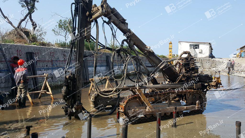 dimensional network.
Micropiles were used for stabilization of gables, strengthening of coastal walls, protection of buried structures and other cases of maintenance and strengthening of soils and structures and strengthening of land. The micropile system was developed in Switzerland and Germany, and the Far East soon became the main market for the technology. The abundance of relatively cheap workers, the shortage of steel, and the urgent need to repair and rehabilitate urban environments all increased the use of micropiles in Europe. Conversely, the slow growth of micropile use in North America was a reflection of the abundance of cheap steel, relatively high labor costs, and the implementation of large projects in suburban areas. Such conditions led to the development of the technique of pile displacement, which were implemented using prescription specifications and had a lower technology than micropiles. Today, the costs of implementation around the world are almost the same, and demand for micropiles continues to grow, especially among geotechnical contractors who have the ability to build and design.
Jet grouting or pressure injection:
Pressure injection or jet grouting was developed in Japan in the early 1970s.
Over the years, with the development of injection equipment and knowledge, various pressurized injection methods have been developed, but the goal of all these methods is to change the soil into a mixture of soil and cement, commonly known as “soil-cement”.
Pressure injection provides the conditions for correcting the shape, size and characteristics of the soil mass.
Introducing the method
Jet grouting is one of the ways to improve and increase the strength and load-bearing capacity of soil in situ. In this method, which can be performed with advanced tools, buried columns of soil and cement mixture are produced by a special injection pump, with high speed (800 to 900 km / h) and also very high pressure (30 to 70 MPa) on site.
Execution methods
In the jet grouting method, a small diameter rod is first drilled in the ground at high speed. When the rod reaches the desired depth, air, water and injection mixture are injected into the soil with a high speed and pressure pump through the nozzles in the tip and wall of the rod.
In this method, the rod rotates at high speed during injection and moves upwards at low speed. This operation breaks the soil structure and mixes thoroughly with the injection mixture. On the other hand, in this method, high injection pressure also increases soil compaction and creates a homogeneous and rigid environment in the soil.
Changes in the injection pressure, the speed of rotation of the rod, and the speed of upward movement of the rod cause a change in the created column. The created cement-soil column will have a resistance in the range of 20 to 200 kg / cm2 and a modulus of elasticity of about 2000 MPa. There are generally three distinct types of pressure injection.
Single Fluid Method
In this method, the fluid is the slurry and the flow under the fluid pressure of 700 bar simultaneously performs abrasion and injection. In this method, the compressive capacity of the cement soil column is more than in the other two methods due to the large volume of slurry. High-pressure injection has the ability to repair all types of soils, from sand and gravel to very sensitive clays.
Double Fluid Method
In this method, a high-pressure flow of cement is used, which is located inside a cone of compressed air. The column diameter of the modified materials in this method is larger than in the first method and a higher degree of soil replacement is obtained.
Triple Fluid Method
In this method, the top outlet of high-pressure water inside the compressed air chamber is used for excavation and the slurry is poured with a low-pressure flow (usually with lower pressure) to replace the drilled soil.
According to the published results of the work done at Delft University, the uniaxial compressive strength of the column performed by the single-fluid method has higher values than other methods of Jet Grouting due to higher cement consumption and lower ratio, resulting in single fluid Jet Grouting column has a higher modulus of elasticity and a higher shear modulus.
What is the dry mixing process (DSM) and for what purpose?
Dry Soil Mixing (DSM) is a general technique of in situ mechanical soil mixing that involves adding a dry additive (commonly called adhesive) and distributing it by airflow. Mechanical mixing is done horizontally or vertically with the impeller rotation of the pedals or by cylinders with shear blades.
Cement slurry is transferred from silos mounted on a rig or mounted on a separate unit. The DSM process and mixing in situ of dry slurry in the soil by compressed air refers to several different items such as cement-lime columns, dry jet mixing, deep dry mixing, column stabilization or mass mixing.
The use of compressed air as a cement slurry transfer medium is an advantage because it requires less grout to increase the required strength in the soil. Therefore, adding dry slurry instead of wet slurry (which is required in wet mixing with jet injection process) in soft soils containing large amounts of water saves cement consumption.
mixing process
The purpose of the mixing process is to adequately distribute and disperse the cement slurry into the soil to provide the best possible conditions for the chemical reaction to occur. In cases where the depth and volume of mixing is large, the mixing process is frequently used in the form of mixed soil columns. The diameter of the columns is usually 0.5 to 1 meter and their depth is in the range of 3 to 25 meters and they are executed only vertically. (Sloping columns with a slope of 4: 1 to 10: 1 are also available)
Subsequently, for shallow depths, mass mixing may be appropriate. Nailing and mass mixing can be performed either in the form of interlocking columns inside a block of vertical elements or in the form of a large volume of soil mixed with a horizontal rotating cylinder with shear heads. Mass mixing is generally performed at depths of 0.5 to 6 meters, but mass mixing is also performed by the method of interfering columns to a depth of about 15 meters. The DSM implementation process is similar to columns and mass mixing and can be divided into three main phases:
1) Penetration of the mixing tool to the required depth
2) in-situ mixing and waiting and spreading the slurry
3) Molecular diffusion and spreading
European standard EN 14679 2005 describes the implementation steps in the form of a 5-step process:
1) Determine the correct position and deployment of the mixing tool
2) Penetration of the mixing shaft to the required depth of modification by separating and simultaneously disrupting the soil structure by the mixing tool
3) After reaching the desired depth, the shaft is pulled out and at the same time the slurry is injected into the soil in the form of granules or powder.
4) The mixing tool rotates horizontally and mixes the slurry.
5) Complete the column